What is ESP8266?
The ESP8266 is a low-cost Wi-Fi microchip with full TCP/IP stack and microcontroller capability produced by Shanghai-based Chinese manufacturer, Espressif Systems. The chip first came to the attention with the ESP-01 module, made by a third-party manufacturer, Ai-Thinker.This small module allows microcontrollers to connect to a Wi-Fi network and make simple TCP/IP connections using Hayes-style commands. It comes with default firmware which supports AT commands. But rather than default firmware you can upload your own program or firmware with Arduino IDE or any other IDE. If you upload a new code the original firmware will be erased.
It costs less than 5 USD and become one of the best choice for IoT projects in very short span of time.
Note: The ESP32 is the ESP8266 successor. It adds a CPU core, faster Wi-Fi, more GPIOs, and supports Bluetooth 4.2 and Bluetooth low energy. Additionally, the ESP32 comes with touch sensitive pins, and built-in hall effect sensor and temperature sensor.
Development Boards
ESP8266 is just the name of the chip, many companies have designed their own boards that use this chip, so there are many different ESP8266 boards on the market. If you don't know the difference between all these different models, you might have a hard time deciding on what board to buy.Some boards have all kinds of features on-board to help developing ESP8266 hardware and software: for example, a USB to Serial converter for programming, a 3.3V regulator for power, on-board LEDs for debugging, a voltage divider to scale the analog input. If you're a beginner, I would definitely recommend a development board. It's easier to get started if you don't have to worry about all these things.
1. Bare-bones boards and boards without a USB interface
If you want to add an ESP8266 to a small project, or if you want a cheaper board, you might want to buy a board that doesn't have features like a USB to Serial converter for programming, a 3.3V regulator for power, on-board LEDs etc. In that case, you can buy one of the many ESP-## modules developed by AI Thinker. They contain just the ESP8266 and the necessary components to run it.The Bare-bone category has 2 sub-categories: boards with a 3.3V regulator on-board, and boards with just the ESP8266 and a flash memory chip, without 3.3V regulator.
If your board doesn't have a 5V to 3.3V regulator, buy one separately. You could use an LM1117-3.3 for example. The on-board 3.3V regulator of most Arduino boards is not powerful enough to power the ESP.
To program the ESP-## modules developed by AI Thinker, you'll need a USB-to-Serial converter. The FTDI FT232RL is quite popular, because it can switch between 5V and 3.3V. It is essential that the USB-to-Serial converter you buy operates at 3.3V. If you buy a 5V model, you will damage the ESP8266. Other than FTDI FT232RL, Arduino Uno is second most popular way to program ESP-##.
2. Development boards with a USB interface
If you want ESP8266 with extra features then choose NodeMCU, SparkFun ESP8266 Thing - Dev Board, SparkFun Blynk Board, Adafruit Feather HUZZAH with ESP8266 Wi-Fi etc. These boards will show up in Device manager (Windows) or in lsusb (Linux) as soon as you plug them in. They have a 3.3V regulator on-board, and can be programmed over USB directly, so you don't need any external components to get it working. The only thing you may need to do, is solder on some headers.Getting Started with Cheaper Boards (ESP8266 ESP-01 developed by AI Thinker)
The ESP8266 ESP-01 boards come with following specifications:- 8Mbit external QSPI flash memory (1MByte)
- 32-bit Tensilica Xtensa LX106 CPU running 80MHz
- 3.3V supply (current can spike 300mA+, depending on mode)
- PCB-trace antenna
- 2 x 4 dual-in-line pinout
- 14.3 x 24.8mm
- 1.5g

Coming to the pin configuration, the ESP-01 module consists of 8 pins and these pins are VCC, GND, TX, RX, RST, CH_PD, GPIO0 and GPIO2.
The following image shows the pin diagram of the ESP-01 Module.

Pin Description
VCC: It is the power pin through which 3.3V is supplied.
GND: It is the ground pin.
TX: This pin is used to transmit serial data to other devices.
RX: The RX pin is used to receive serial data from other devices.
RST: It is the Reset Pin and it is an active LOW Pin. (ESP8266 will reset if the RST pin receives LOW signal).
CH_PD: This is the chip enable pin and it is an active HIGH Pin. It is usually connected to 3.3V.
GPIO0: The GPIO0 (General Purpose I/O) Pin has dual functions – one for normal GPIO Operation and other for changing the Mode (Programming/Normal). Start in Programming mode if receive LOW signal.
GPIO2: This is GPIO Pin.
ESP8266 ESP-01 Boot Mode Selection
ESP8266 WiFi Module has two modes of operation: Programming Mode and Normal Mode.
Programming Mode: In Programming Mode, you can upload the program or firmware to the ESP8266 Module. In order to enable the Programming Mode, the GPIO0 pin must be connected to GND.
Normal Mode: Leave GPIO0 pin as it to run in normal mode. In Normal Mode, the uploaded program or firmware will run normally.
Also, the RST (Reset) will play an important role in enabling Programming Mode. The RST pin is an active LOW pin and hence, it is connected to GND through a Push Button. So, whenever the button is pressed, the ESP8266 Module will reset.
Testing Default Firmware (Official AT Firmware) Code on ESP8266 ESP-01
To test default AT firmware on ESP8266, you need A USB to Serial TTY adapter to connect with ESP8266, FTDI FT232RL may work but if you didn’t get the wiring right you will fried the ESP8266. One of the best and safe option is to use the Arduino Uno as a Bridge, bypassing everything in the uno and talking to the ESP8266 directly.Arduino Uno have an on-board USB-to-Serial converter, you can use that. So heres how this works. You can connect the reset pin on the Uno to GND to bypass the Arduino boot loader (If you Arduino Uno is not genuine, It may work without connecting reset pin to GND), then connect TX to TX, RX to RX, GND to GND, VCC and CH_PD to 3.3v, and leave the GPIO0, GPIO2, RST pin as it (Normal Mode run the default firmware code inside ESP8266).
VCC to 3.3V
GND to GND
TX to TX of Arduino UNO
RX to RX of Arduino UNO
CH_PD to 3.3V

1. Accessing ESP8266 from Arduino Serial Monitor in the Arduino IDE
Once you have it wired up, you should be able to use the Arduino Serial Monitor in the Arduino IDE to access the ESP8266. Remember you’ll connect to the port the Arduino is on.As TX is connected to TX and RX is connected to RX, it is just like extending the wires for TX and RX and Serial Monitor in the Arduino IDE will access the ESP8266 directly.

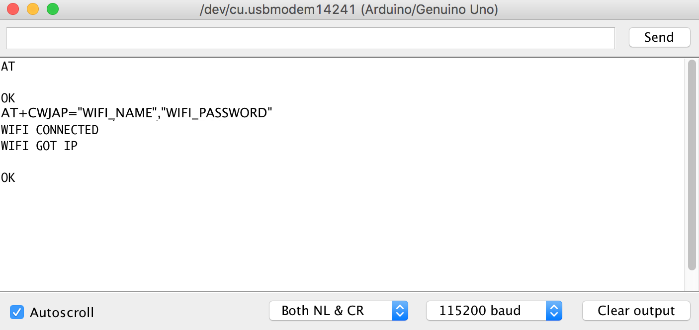
Next make sure you choose “Both NL & CL” then adjust the Baud rate. My module was talking on 115200 baud but I’ve heard other models on 9600.
At this point you should be able to send an “AT” command and get an “OK” response. WoHoo! you’re talking to the ESP8266.
Now send "AT+GMR" to retrieve the Firmware version and keep it for future reference.
To connect wifi use AT+CWJAP="SSID", "Password" For more commands please refer
2. Accessing ESP8266 from Arduino Uno code
Remember one thing here, to access ESP8266 from arduino you need to connect RX pin of arduino to TX pin of ESP8266 and TX pin of arduino to RX pin of ESP8266 as here we are not just extending the wire but arduino is directly communicating to ESP8266. Also the RST pin of arduino should not be connected to GND, it should be left as it.To access ESP8266 from code the wiring will have the TX of the Uno connected to the RX on the ESP8266 and the RX on the Uno talking to the TX on the ESP8266, but don’t do it yet. PROBLEM theres only one serial on the Uno but we need it for connecting the IDE to the UNO since it works over the USB Serial on the same pins. We can’t use one Serial for both. Thankfully we can use some code called SoftwareSerial to make a Virtual Serial port on the Arduino. This means that instead of connecting to the TX/RX we’ll connect to another pin set and have SoftwareSerial send commands to those pins instead.
Ok lets use pin 10 as RX and pin 11 as TX of Arduino. That can be achieved by using SoftwareSerial library of Arduino.
VCC to 3.3V
GND to GND
TX to 10 of Arduino UNO
RX to 11 of Arduino UNO
CH_PD to 3.3V
First we need to setup the virtual serial for the module. We’ll include the library and define the variable
#include <SoftwareSerial.h>
#define RX 10
#define TX 11
SoftwareSerial esp8266(RX,TX);
From here on we’ll talk to the ESP8266 through “esp8266” and we’ll talk to the IDE through “Serial”. Let’s try it in our setup function
void setup() {
Serial.begin(9600);
esp8266.begin(115200);
}
Note that we set the Serial connection to a 9600 baud rate and the esp8266 connection to a 115200 baud rate. Make sure to set your IDE Serial Monitor to the right baud and set the esp8266.begin value to the baud rate of the module you confirmed earlier.
OK ready for the whole code base? here is the code Basically there’s a helper function called “sendCommand” that takes a command, a timeout value and the expected result as input.
#include <SoftwareSerial.h>#define RX 10 #define TX 11 int countTrueCommand; int countTimeCommand; boolean found = false; SoftwareSerial esp8266(RX,TX); void setup() { Serial.begin(9600); esp8266.begin(115200); sendCommand("AT",5,"OK"); sendCommand("AT+CWMODE=1",5,"OK"); } void loop() { sendCommand("AT+CWLAP",20,"OK"); } void sendCommand(String command, int maxTime, char readReplay[]) { Serial.print(countTrueCommand); Serial.print(". at command => "); Serial.print(command); Serial.print(" "); while(countTimeCommand < (maxTime*1)) { esp8266.println(command);//at+cipsend if(esp8266.find(readReplay))//ok { found = true; break; } countTimeCommand++; } if(found == true) { Serial.println("Success"); countTrueCommand++; countTimeCommand = 0; } if(found == false) { Serial.println("Fail"); countTrueCommand = 0; countTimeCommand = 0; } found = false; }
Flashing Custom Program on ESP8266 ESP-01
ESP8266 ESP-01 is itself have a microcontroller with 2 GPIO pins, We can install our custom code or micro OS in this. The EspressIf itself provide various framework for ESP8266. Let's flash custom program first then we will check other options.Even though ESP8266 WiFi Module is manufactured by Espressif Systems, the SoC is used by many third party manufacturers to implement their own custom modules. In my case, I have the ESP8266 ESP-01 Module by AI-Thinker.
Before proceeding into the process of custom program flash, it is important to configure the ESP8266 WiFi Module in Programming Mode and Arduino UNO as the USB to Serial Interface so GPIO0 pin should be connected to GND, RX to RX and TX to TX.
VCC to 3.3V
GND to GND
TX to TX of Arduino UNO
RX to RX of Arduino UNO
GPIO0 to GND
RST to GND through Push Button
CH_PD to 3.3V
Once the ESP8266 Module is powered ON, Push the RST button and open the Arduino IDE. In the Board options (Tools –> Board), select the “Generic ESP8266” Board. Select the appropriate port number in the IDE. Now, open new Sketch paste the code below, connect led on pin 2. Here, 2 means GPIO2 pin of the ESP8266 Module. Before you hit the upload make sure that GPIO0 is connected to GND first and then press the RST button.
void setup()
{
  pinMode(2, OUTPUT);
}

void loop()
{
  digitalWrite(2, HIGH);
  delay(1000);
  digitalWrite(2, LOW);
  delay(1000);
}
Now hit the upload button and the code will take a while to compile and upload. You can see the progress at the bottom of the IDE. Once the program is successfully uploaded, you can remove the GPIO0 from GND. The LED connected to GPIO2 will blink.
Updating/Flashing Official AT Firmware on ESP8266 ESP-01
The Official AT Firmware can be installed for two reasons: If you want to update the ESP8266 Firmware to its latest version or to completely install the new firmware (in case it was overwritten by any other program).We will flash the official Espressif Systems’ firmware for ESP8266 Module using the official ESP8266 Flasher Tool provided by Espressif Systems which is the ESP8266 FLASH DOWNLOAD TOOL and Arduino UNO as the USB to Serial Interface.
Please note down the current Firmware version that you have retrieved by "AT+GMR" and make the circuit configuration same as during custom program upload.
1. Downloading the Latest ESP8266 Firmware
There are two types of SDK or Software Development Kits for ESP8266: Non-OS SDK and RTOS SDK. The Non-OS SDK, as the name suggests, isn’t based on any OS. Using this SDK, you can compile IOT_Demo and AT Commands. The RTOS SDK on the other hand is based on FreeRTOS. I’ll be using the Non-OS SDK (well, technically, the Firmware files based on the Non-OS SDK). The ESP8266 Firmware files are in the form of Binary Files i.e. .bin files.Now since I will be using only the AT Command Set of the ESP8266, I will download only the Bin Files associated with the AT Commands. In order to download the AT Commands Firmware for ESP8266, visit the official link here or directly download from this link. You can download other version as well as per your choice.
2. Downloading the ESP8266 Flash Download Tool
You can directly download ESP8266 Flash Download Tool from this link.3. Installing the Firmware in ESP8266
After opening the ESP8266 Flash Download Tool, you need to select the firmware files that we need to install. You need to upload four files at four different addresses. The following table will give you the list of files and their corresponding addresses.NOTE: This list is for Firmware over the Air (FOTA) Flash Memory Mapping for ESP8266 Modules with 1MB of Flash. For other flash sizes, please refer to the ESP8266 Getting Started Guide from this link.
File
|
Address in Flash Memory
|
boot_v1.7.bin
|
0x00000
|
user1.1024.new.2.bin
|
0x10000
|
esp_init_data_default.bin
|
0xFC000
|
blank.bin
|
0xFE000
|
In the ESP8266 Download Tool, in the SPI Download Tab, select the necessary files in the “Download Path Config” option by click on the (…) button. Also, add the corresponding addresses in the space provided.
After selecting the four files and filling in the Addresses, set the crystal frequency to 26MHz (it is usually 26MHz but in case your ESP8266 board has a different crystal, enter that value). Next select the flash size. Since I have a 1MB flash on-board, I have selected the 8Mbit (which is equal to 1MB) flash size option.
Finally, select the correct COM Port and set the baud rate to 115200. Make sure that all the serial terminal are closed. Now click on START button. The flashing of the firmware in ESP8266 should begin. If you notice in the ESP8266 Firmware Flash Tool, the moment you click on START, you will get two MAC Address as AP and STA and also information about the Module in the DETECTED INFO section.
If everything goes well, the ESP8266 Module must be updated with new firmware. If there is any error, disconnect the USB cable, connect it once again, and after clicking on START, push the Reset button of the ESP8266.
You will get a FINISH message on the Tool and you can close the tool after this. Disconnect the GPIO0 from GND and reset the device. Open the serial monitor of Arduino once again and check for new firmware.
Comments and Questions welcome! Thanks for reading.

